
Views: 0 Author: Site Editor Publish Time: 2026-10-17 Origin: Site


Ground-mounted solar projects offer immense scalability for developers exploring open-field terrain. These large arrays unlock massive energy generation potential far beyond standard rooftop limits. However, project margins are frequently lost to unexpected soil conditions. Installers also face steep setbacks from improper foundation selection and inefficient racking assembly. Transitioning from residential roof mounts to ground-based arrays requires a critical strategic shift. Scaling up to utility-level projects means moving away from standardized kits. You must rely on site-specific structural engineering instead.
This guide breaks down the evaluation criteria for selecting foundations, racking materials, and structural configurations. You will discover practical ways to ensure code compliance across varying topographies. We also cover methods to control labor costs effectively. Finally, we outline actionable steps to mitigate long-term maintenance risks and protect your asset lifecycle.
Foundation matching is non-negotiable: Soil composition (cohesion, frost depth, rock density) dictates the choice between driven piles, ground screws, and ballasted systems.
Material selection impacts lifetime ROI: Galvanized and carbon steel offer superior load-bearing capacity for harsh environments, though aluminum remains viable for lighter, highly corrosive micro-climates.
Adjustability adds yield but introduces risk: Moving parts in an adjustable structure increase maintenance overhead; the yield-to-cost ratio must be validated geographically.
Labor is the hidden cost: Utility-scale procurement must prioritize pre-assembled components and high-tolerance racking to minimize on-site labor hours.
A ground mount solar system is only as reliable as the earth beneath it. Skipping comprehensive geotechnical analysis leads to disastrous outcomes. Installers often experience foundation refusal during installation when encountering unexpected bedrock. Alternatively, sites suffer from frost-heave failure post-deployment because engineers misjudged the frost line. You cannot afford to guess soil behavior on a multi-megawatt array.
A proper site assessment relies on a strict set of evaluation criteria. We recommend structuring your geotechnical review around these specific elements:
Soil Compaction & Type: You must classify the earth accurately. Sandy soil lacks the friction needed for traditional piles. Loamy earth generally accepts standard driving methods. Cohesive clay provides excellent lateral support. Bedrock requires specialized drilling or ballasted solutions.
Environmental Loads: Local codes dictate structural requirements. Follow ASCE 7 or your local equivalent. These standards define maximum wind speed resistance. They also establish mandatory snow load capacities based on historical weather patterns.
Topography: Managing undulating terrain requires precise engineering. Racking systems typically handle slope tolerances up to 10–15% natively. Steeper grades demand heavy civil grading, which rapidly increases project expenses.
Failing to pull a site-specific geotechnical report introduces severe implementation risks. Manufacturers often void structural warranties if installations proceed without empirical soil data. This oversight leaves the installer entirely liable for system settling, panel misalignment, and structural fatigue over time.
Conduct pull testing at multiple locations across the parcel to account for varying soil zones.
Involve a structural engineering partner before finalizing your racking procurement.
Verify groundwater tables to anticipate seasonal soil saturation issues.
Matching the foundation to your specific soil report prevents costly mobilization delays. Installers generally choose from three primary solution categories based on the geotechnical data.
Driven piles using W-sections or C-channels represent the most cost-effective option for large-scale sites. They perform exceptionally well in cohesive soil. Driven piles offer high installation speed, allowing crews to cover acres of ground quickly. However, they carry a high risk of refusal in rocky soil. Hitting sub-surface boulders halts production and damages equipment.
Ground screws and helical piles serve as the ideal alternative for difficult terrain. They excel in rocky, sandy, or freeze-thaw prone environments. Helical flights bite into loose soil, generating massive uplift resistance. While ground screws carry a higher material cost, they eliminate the need for concrete. They also bypass the refusal risks associated with standard driven piles.
Concrete ballasts remain necessary for restricted sites. Brownfields, capped landfills, and highly corrosive soils often prohibit deep ground penetration. Installers use cast-in-place forms or pre-cast concrete blocks. This method avoids soil disturbance completely. However, ballasts incur the highest logistical and material costs due to heavy freight and extensive site preparation.
Your decision framework should weigh equipment mobilization costs against material expenses. Compare the rental rates of heavy pile drivers against rotary excavators. Always factor in local site penetration restrictions before finalizing your foundation strategy.
Foundation Evaluation Matrix
| Foundation Type | Ideal Soil Conditions | Equipment Needed | Installation Speed |
|---|---|---|---|
| Driven Piles | Cohesive clay, loamy soil | Heavy pile driving rig | Fast |
| Ground Screws | Rocky, sandy, frost-prone | Rotary excavator attachment | Medium |
| Concrete Ballasts | Brownfields, capped landfills | Concrete trucks, heavy cranes | Slow |
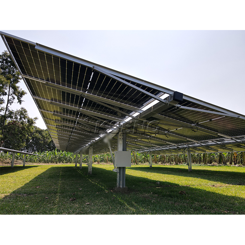
Installers must balance upfront material costs against structural integrity. They must also ensure 25-year corrosion resistance for every component. Choosing the wrong metal compromises the entire solar asset. You must evaluate materials based on local climate conditions and structural load demands.
Aluminum configurations offer distinct advantages for specific applications. Aluminum is significantly lighter and highly corrosion-resistant. Field crews find it much easier to handle on-site, reducing physical fatigue. These traits make aluminum the best choice for standard residential installations or light commercial systems. It also performs brilliantly in coastal areas where salty air rapidly degrades basic steel.
However, heavy-duty applications require robust alternatives. A Carbon Steel Ground Solar Mounting Bracket is the industry standard for high wind and heavy snow regions. Carbon steel prevents structural fatigue under immense environmental stress. Installers specifically utilize hot-dip galvanized steel or zinc-aluminum-magnesium (MAC/ZAM) coated steel to ensure longevity.
You must perform a strict trust and evidence check on steel coatings. Evaluate coatings based on ISO 14713 guidelines. This framework determines the expected zinc coating life across specific atmospheric corrosivity categories ranging from C1 (very low) to C5 (very high). Avoid suppliers offering thin electro-galvanization for ground mounts. Electro-galvanized parts rust quickly when exposed to soil moisture and outdoor elements.
Mixing dissimilar metals without isolation pads, leading to galvanic corrosion.
Assuming inland soils are non-corrosive without checking pH and sulfate levels.
Purchasing standard raw steel brackets to save upfront capital.
Solar arrays generate the most power when modules directly face the sun. The structural configuration you choose determines both your energy yield and your operational overhead. Installers typically evaluate two primary solution approaches.
Standard fixed-tilt systems provide the lowest capital expenditure. They contain zero moving parts, resulting in highly predictable operations and maintenance (O&M). Engineers optimize the fixed angle for a single seasonal peak. This approach guarantees reliable base-load generation without requiring ongoing manual intervention.
Seasonal adjustable structures offer a more dynamic approach. They allow manual tilt changes throughout the year. Field crews can set the array to 15° in summer to capture high overhead sun. They can then adjust it to 45° in winter to maximize low-angle light and shed heavy snow accumulation.
An adjustable solar structure can increase energy yield by 5–15%. However, this yield-to-cost ratio requires strict geographic validation. Installers must calculate if the localized generation bonus offsets the labor cost. Sending crews to manually adjust a large array twice a year represents a significant operational expense.
Adjustability introduces physical risk. Adjustable pivot points represent potential failure nodes. They are highly susceptible to rust and mechanical fatigue. You must engineer these connections with industrial-grade bushings and specialized fasteners. Neglecting hardware quality on moving parts guarantees premature system failure.
Scalability transforms supply chain logistics. Moving from 50kW commercial sites to multi-megawatt fields requires a completely different procurement approach. You can no longer rely on standard off-the-shelf residential kits. Utility-level deployments demand highly engineered, scalable solutions designed for rapid deployment.
When specifying a Utility-Scale Solar Racking System, you must apply three crucial evaluation lenses:
Pre-assembly: Determine how the manufacturer ships the materials. Do they provide pre-assembled folding A-frames, or do they ship loose parts? Unboxing and sorting loose parts increases labor hours by up to 40%. Factory pre-assembly dramatically reduces field labor.
Tolerance & Flexibility: Evaluate the racking adaptability. Can the structure easily accommodate varied module sizes, including large-format bifacial panels? Furthermore, the system must absorb installation inaccuracies. If field crews drive a pile slightly off-center, the racking brackets must offer enough tolerance to correct the alignment without requiring extraction.
Supply Chain Compliance: Scrutinize the origins of your components. Ensure the structural materials are sustainably sourced. If you operate in the US, verify compliance with domestic content requirements to qualify for IRA tax incentives. Proper documentation unlocks significant project capital.
Take proactive next-step actions before finalizing any procurement. Request stamped engineering letters from your racking suppliers. Demand full pull-test documentation matching your specific soil type. Never issue purchase orders without verifying these engineering credentials.
Successful ground mount design hinges on precision and localized engineering. You must match your foundation choice directly to empirical soil data. Selecting proper racking materials guarantees survival against 25+ years of local weather loads. Furthermore, prioritizing pre-assembled, high-tolerance structural designs drastically limits expensive on-site labor.
Never rely on generalized assumptions when designing open-field arrays. Base every decision on hard data, including geotechnical reports, documented pull tests, and verified structural engineering stamps. Guesswork in civil engineering always results in eroded project margins.
As your next step, contact a certified structural engineering partner or a tier-one racking manufacturer. Have them run a comprehensive, site-specific load calculation for your upcoming project portfolio. Securing this data early ensures a profitable, code-compliant deployment.
A: Most systems require a minimum clearance of 24 to 36 inches. This height ensures adequate space for heavy winter snow shedding. It also simplifies summer vegetation management under the array. For bifacial modules, higher clearance allows optimal back-side light reflection, maximizing your total energy gain.
A: Always consult your site-specific geotechnical report. Use driven piles for cohesive, loamy soils where installation speed is critical. Choose ground screws if the report indicates high rock density, sandy earth, or a deep frost line. Ground screws resist severe frost heave and eliminate subsurface refusal risks.
A: Raw steel rusts, but engineered solar brackets use heavy protective coatings. High-quality carbon steel relies on hot-dip galvanization or advanced MAC/ZAM (zinc-aluminum-magnesium) coatings. These industrial treatments guarantee 25+ year lifespans, protecting the underlying steel even in highly corrosive or moist soil conditions.
A: Yes, adjustable systems demand scheduled oversight. Moving parts require periodic torque checks to ensure fasteners remain tight after seasonal adjustments. You must also conduct routine visual inspections of all pivot points and industrial bushings. Catching early signs of mechanical fatigue or rust prevents structural failure.





