
Views: 0 Author: Site Editor Publish Time: 2026-09-10 Origin: Site


Selecting the wrong racking system introduces critical geotechnical risks. It inflates upfront capital expenses through excessive labor. This misstep also jeopardizes the 25-year structural integrity of your solar asset. A successful deployment requires careful planning. You must match the racking structure and foundation to site-specific topography. Soil composition, regional wind loads, and heavy snow accumulation matter greatly. Long-term LCOE goals also dictate your ultimate success. Without a clear strategy, minor site variables quickly escalate into major deployment delays.
This guide categorizes the primary types of ground mount solar systems by foundation, material, and structural design. We provide a transparent evaluation framework for project developers, EPCs, and commercial buyers. You will learn how to navigate harsh geotechnical realities. You will also discover how to balance material capital trade-offs effectively. Finally, we explore advanced coatings and specialized structural designs to optimize your next utility-scale deployment.
Geotechnical realities dictate foundation choices; there is no universal mounting solution.
Material selection (e.g., Aluminum vs. Zn-Al-Mg Steel) dictates the balance between upfront procurement costs and long-term O&M (corrosion resistance).
Non-traditional structures like vertical arrays are shifting the financial models for agrivoltaics and high-latitude projects.
Procurement shortlisting must prioritize local code compliance (e.g., ASCE 7), static/dynamic load testing, and realistic installation timelines over raw material costs.
Evaluating solar structures requires more than simply comparing material price tags. You must conduct a holistic site analysis. This analysis ensures you choose a system capable of enduring decades of environmental stress. We evaluate these systems across three critical dimensions.
The ground beneath your solar array dictates every foundation decision. Soil cohesion plays a massive role in stability. Sandy soils lack the friction required to hold driven piles during uplift events. Dense clay offers excellent holding power but expands when wet. Bedrock depth is another critical variable. Hitting shallow bedrock midway through trenching forces a costly pivot away from standard piles.
Frost lines also demand careful attention in colder climates. Installers must drive foundations below the maximum frost depth. Otherwise, frost heave will push the piles upward. This movement twists the racking and shatters the solar modules. Finally, severe land grading limits foundation viability. Steep slopes require specialized articulating joints and custom pile lengths to maintain an even module plane.
Solar project financing requires a delicate balance between upfront capital expenditure (CAPEX) and long-term operational expense (OPEX). Heavy machinery costs dominate the initial installation phase. Renting hydraulic pile drivers drives up CAPEX quickly. However, this machinery drastically reduces human labor hours.
Material choices directly impact OPEX. You might save money purchasing standard galvanized steel upfront. Yet, standard galvanizing may fail in high-salinity soils. This failure accelerates rust. Active rust mitigation and structural repairs over a 25-year lifespan easily consume those initial savings. Land-use efficiency also factors into this balance. High-density layouts reduce land acquisition costs but complicate vegetation management. You must weigh these long-term maintenance realities during the procurement phase.
Structural failure is an unacceptable outcome for any solar asset. You must ensure the selected system meets rigorous regional engineering standards. In the United States, engineers rely heavily on ASCE 7 guidelines. These codes dictate exact wind speed and snow load limits based on county data.
Coastal regions require racking engineered for hurricane-force wind shear. Northern regions demand high snow-load capacity to prevent the aluminum frames from buckling under heavy ice. Seismic requirements also dictate connection tolerances in earthquake-prone zones. However, you must avoid over-engineering the system. Demanding excessive steel thickness for a low-wind, flat inland site unnecessarily inflates costs. Smart engineering matches the metal thickness exactly to the verified environmental threat.
Every solar array requires a robust connection to the earth. The foundation transfers environmental loads from the panels safely into the ground. We classify these systems based on how they anchor into the soil.
Concrete anchors provide maximum stability when traditional soil penetration is impossible. You deploy these systems across sites with severe subsurface restrictions.
Mechanism: This approach utilizes cast-in-place concrete footings, pre-cast blocks, or ballasted tubs. Installers place the racking directly onto these heavy concrete anchors. The sheer weight of the concrete prevents the system from lifting during high winds.
Best For: We highly recommend the Concrete Foundation Ground Mount for brownfields and closed landfills. Environmental regulations prohibit driving steel piles into landfills. Piles would pierce the protective geomembrane liner below the soil. Concrete foundations sit safely on the surface. They also excel in rocky terrain where pile drivers cannot penetrate. Highly corrosive soils also necessitate concrete to protect steel components from rapid degradation.
Implementation Risks: Concrete introduces significant logistical hurdles. High material transport costs impact remote site budgets heavily. Pouring concrete on-site requires longer installation timelines due to mandatory curing periods. This method also features a higher labor dependency. Crews must build forms, pour cement, and level the footings manually.
When soil conditions permit, direct earth penetration offers rapid deployment. These foundations dominate the utility-scale solar market.
Mechanism: Installers use hydraulic machinery to ram steel posts directly into the soil. The friction between the soil and the steel holds the pile firmly in place. Alternatively, ground screws feature helical threads. Machinery drills these massive screws into the earth, providing excellent pull-out resistance.
Comparison: Driven piles offer much faster deployment than concrete. They drastically lower labor costs. A skilled crew can drive hundreds of piles in a single day. However, this method remains strictly reliant on favorable soil conditions. You cannot use driven piles if the site contains minimal cohesion or large rock strata. Ground screws handle loose, sandy soils better than straight piles, but they still fail against solid bedrock.
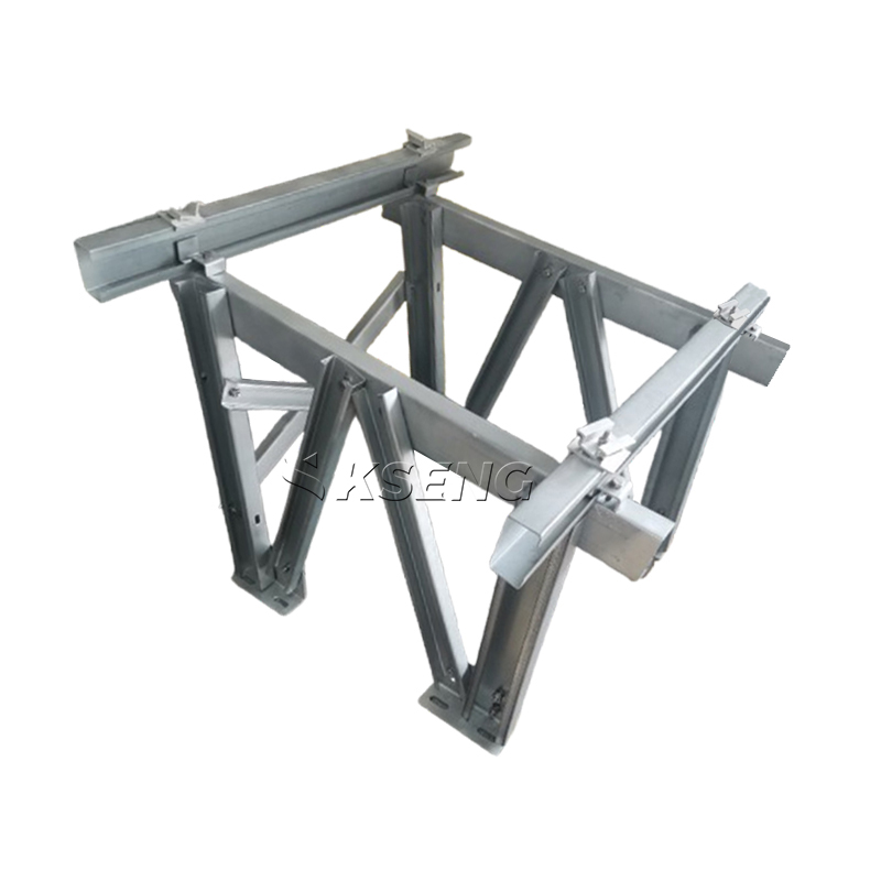
The structural material dictates both the installation experience and the long-term durability of the array. Developers primarily choose between lightweight aluminum and advanced steel alloys.
Aluminum offers distinct metallurgical advantages for specific environmental challenges. It provides an excellent alternative to heavy steel.
Evaluation: Aluminum is naturally oxidation-resistant. It forms a microscopic protective oxide layer upon exposure to air. This layer prevents deep structural corrosion. Aluminum is also highly malleable, allowing manufacturers to extrude complex, custom profiles easily. Most importantly, it is significantly lighter than steel.
Use Case: You should deploy an Aluminum Ground Mount in coastal environments with high airborne salinity. The metal resists salt spray exceptionally well. It also shines in projects requiring rapid on-site manual handling. Workers can lift and position aluminum rails without heavy machinery. Finally, sites with strict soil weight restrictions benefit greatly from this lightweight structure.
Skeptical Lens: Aluminum is subject to higher raw material market volatility. This unpredictability complicates long-term procurement budgets. Furthermore, it generally carries a higher initial CAPEX compared to standard galvanized steel. Aluminum also has lower tensile strength than steel. This reality often requires thicker structural profiles to achieve similar wind load ratings.
Standard hot-dip galvanizing is losing ground to advanced metallic coatings. Zinc-Aluminum-Magnesium steel represents the cutting edge of structural protection.
Evaluation: This advanced steel utilizes a unique alloy coating. The zinc, aluminum, and magnesium combine to offer superior corrosion resistance. This alloy provides a remarkable "self-healing" property. When installers cut the metal or weld joints on-site, the magnesium-rich layer migrates over the exposed steel. This chemical reaction seals the wound, outperforming traditional hot-dip galvanizing significantly.
Use Case: A Zn-Al-Mg Steel Ground Mount is ideal for massive utility-scale projects. These sites demand maximum structural rigidity. The steel easily handles high wind-load endurance requirements. It provides an optimized LCOE over a 30-year lifespan by virtually eliminating mid-life rust remediation costs.
Skeptical Lens: Steel remains incredibly heavy. This heavier component weight increases shipping logistics. It burns through transportation budgets quickly. Installers strictly require heavy machinery for placement. Manual handling of these large steel beams is highly inefficient and poses safety risks.
Material Comparison for Ground-Mount Racking
| Feature | Aluminum Alloy | Zn-Al-Mg Steel |
|---|---|---|
| Corrosion Resistance | Excellent (Natural Oxidation) | Superior (Self-healing coating) |
| Component Weight | Lightweight (Manual handling possible) | Heavy (Requires machinery) |
| Initial CAPEX | Generally Higher | Moderate |
| Tensile Strength | Moderate | Very High |
| Best Environment | Coastal / C5 Marine Zones | Utility-scale / High Wind Zones |
Beyond foundations and materials, the geometric design of the structure heavily influences energy yield. Choosing the correct orientation maximizes financial returns.
Most commercial arrays utilize fixed-tilt structures. They hold panels at a static angle optimized for the local latitude. Fixed systems offer absolute reliability because they lack moving parts. Single-axis and dual-axis trackers actively follow the sun across the sky. Trackers boost energy yield significantly. However, they introduce moving mechanical components. These motors and bearings require strict maintenance budgets. Developers must balance the higher yield against the inevitable mechanical OPEX.
Traditional south-facing arrays consume massive amounts of land. Vertical systems flip this dynamic entirely, introducing new possibilities for constrained sites.
Evaluation: Installers construct these arrays vertically at a strict 90-degree angle. They typically utilize bifacial modules. The panels face East and West. This orientation captures the morning and evening peak sun. It creates a unique "M-shaped" energy generation curve. This curve often aligns better with grid demand peaks than a traditional mid-day solar curve.
Use Case: The Vertical Ground Mount dominates the growing agrivoltaics sector. The vertical design leaves wide avenues between rows. This allows heavy farm machinery, tractors, and combine harvesters to pass easily. Farmers can grow crops right alongside energy production. Vertical arrays also excel in areas with heavy snow accumulation. They boast zero snow-shedding issues because snow simply cannot accumulate on a vertical surface. They also function beautifully as property boundary fences.
Implementation Risks: Vertical structures face unique physics. The 90-degree angle acts as a massive wall. It catches the wind, creating a severe "sail effect." This requires strict wind-load engineering. Engineers must specify much deeper foundations to counteract this lateral shear. Additionally, developers must adjust their financial models. Yield profiles differ significantly from traditional south-facing setups.
Procuring a ground mount system requires a logical, step-by-step validation process. Skipping these steps guarantees budget overruns and installation delays. Follow this sequence to secure the right racking platform.
Execute a Geotechnical Pull Test. Never select a foundation type based on assumptions or adjacent property data. Mandate on-site soil boring. Conduct physical axial and lateral pull-out tests. These tests validate exact foundation suitability. They prove whether the soil can actually hold the specified pile under wind stress.
Map Features to Project Outcomes. Align your material choices with local economic realities. For example, if local labor rates are exceptionally high, over-indexing on an easy-to-assemble aluminum structure makes financial sense. The reduction in expensive labor hours may easily offset the higher material CAPEX of the aluminum itself.
Vet Warranty & Bankability. Scrutinize the manufacturer's warranty against your actual environmental conditions. Many warranties contain hidden exclusions. You must verify if the Zn-Al-Mg coating warranty actually covers C5 marine environments. A warranty is useless if it excludes high-salinity zones when your site borders the ocean.
Request Value Engineering. Engage structural engineers early in the design phase. Challenge them to strip out unnecessary metal weight. They can adjust beam spacing or pile depths based on exact topography. This value engineering maintains local code compliance while reducing total steel tonnage and shipping costs.
Deploying a reliable solar asset requires careful alignment of site realities and structural capabilities. The right ground-mount system harmonizes geotechnical data, material science, and long-term LCOE goals. You cannot force a driven pile into bedrock, nor should you deploy standard steel in harsh marine zones. Aluminum provides incredible workability and corrosion resistance. Advanced Zn-Al-Mg steel delivers unmatched structural rigidity and self-healing longevity. Furthermore, innovative vertical designs are unlocking dual-use land opportunities previously thought impossible.
Take immediate action to protect your investment. Initiate a comprehensive site survey today. Procure detailed geotechnical reporting before making any material deposits. Request exact structural load models from vetted racking suppliers. By prioritizing engineering validation over raw material costs, you ensure your solar array produces profitable energy for decades to come.
A: Cost heavily depends on your site soil. Driven piles are usually the cheapest option. They require less labor and deploy rapidly. However, this is only true if soil conditions permit driving. If your site contains shallow bedrock, you must use concrete foundations. Concrete requires more labor and materials, increasing upfront costs.
A: They last significantly longer. Zn-Al-Mg coatings offer exceptional durability. The magnesium creates a dense protective layer over time. This layer provides a "self-healing" effect. When installers cut or scratch the metal, the coating migrates to protect the exposed steel. This extends structural lifespan well beyond traditional hot-dip galvanizing.
A: Yes, they can. However, they require strict engineering. Vertical arrays face significant wind shear due to the "sail effect." Engineers must specify deeper foundations to counteract these lateral forces. They also use reinforced structural profiles. Proper modeling ensures they meet local wind speed regulations without failure.
A: Yes, they often do. Pouring concrete introduces environmental concerns. Local authorities may require extensive environmental impact reports. This is especially true for sensitive habitats. In contrast, removable steel piles usually face simpler permitting. They do not permanently alter the soil chemistry or drainage patterns.





