Views: 0 Author: Site Editor Publish Time: 2026-09-04 Origin: Site


For solar EPCs and installers, ground mount profit margins are won or lost in the design and site preparation phase. Navigating unpredictable terrain requires absolute precision before the first piece of steel ever arrives on site. Mismatched foundation choices or under-engineered racking systems routinely lead to failed inspections, stalled timelines, and blown labor budgets. Installers frequently discover too late that poor upfront planning causes massive downstream construction delays. We created this guide to provide technical decision-makers with a clear, evidence-based framework for evaluating ground mount structures. You will learn how to mitigate geotechnical risks effectively. We will also show you how to select the right racking configurations to ensure smooth execution on commercial and utility-scale projects. Every site presents unique challenges, from erratic soil profiles to rigorous wind load regulations. By standardizing your evaluation process, you protect project profitability and guarantee structural integrity.
Geotechnical realities dictate foundation choices; skipping a pull test often negates any front-end material savings.
Pile ground mounting systems remain the industry standard for cohesive soils, while solar ground screws provide a necessary fallback for rocky or dense terrain.
Optimizing your ground mount solar system design requires balancing local load ratings (ASCE 7 compliance) with labor-efficient structural materials like an aluminum ground mount rack.
Selecting a racking partner should hinge on their internal engineering support, stamped structural drawings, and installation tolerances.
The foundation acts as the crucial anchor for your entire project. It represents the highest-risk variable in any ground-mounted array. You must evaluate subsurface conditions accurately before ordering materials. Selecting the wrong base escalates labor costs rapidly. It also forces teams to bring in expensive heavy machinery at the last minute.
Different soil compositions demand specific foundation strategies. We categorize the solutions into three primary methodologies.
Driven Piles
A Pile Ground Mounting System remains the most common choice for commercial sites. It works best in loam, clay, and cohesive soils containing minimal rock. Driven piles offer the fastest installation time per megawatt. They also boast the lowest upfront material cost. However, you face a major risk of refusal in rocky soil. When a pile hits solid bedrock, you must pre-drill the holes. This unexpected step dramatically increases labor and equipment expenses.
Helical Anchors
When you encounter rocky, dense, or heavily varied soil conditions, driven piles often fail. In these scenarios, a Solar Ground Screw provides a necessary and robust alternative. Ground screws bypass minor subsurface obstacles without experiencing refusal. They deliver exceptionally high pull-out resistance. We highly recommend them for regions experiencing extreme frost heave. The threads lock into the soil below the frost line, preventing seasonal shifting.
Ballasted Foundations (Concrete Blocks)
Certain sites prohibit ground penetration entirely. Landfills, brownfields, and highly corrosive soils require surface-level anchoring. Concrete ballasted foundations offer zero ground disturbance. The trade-off includes extremely high concrete costs. Furthermore, moving heavy concrete blocks increases logistical staging complexity across the site.
Never guess your soil composition. You must mandate a comprehensive geotechnical report. Follow this up by conducting on-site pull tests before committing to a foundation methodology. Skipping the pull test almost always negates any front-end material savings you thought you achieved.
Foundation Selection Matrix
| Foundation Type | Ideal Soil Conditions | Primary Advantage | Key Implementation Risk |
|---|---|---|---|
| Driven Piles | Loam, clay, cohesive soil | Fastest install speed | Refusal in rocky terrain |
| Ground Screws | Rocky, dense, frost-prone | High pull-out resistance | Slightly slower installation |
| Ballasted Blocks | Landfills, brownfields | Zero ground penetration | High concrete logistics cost |
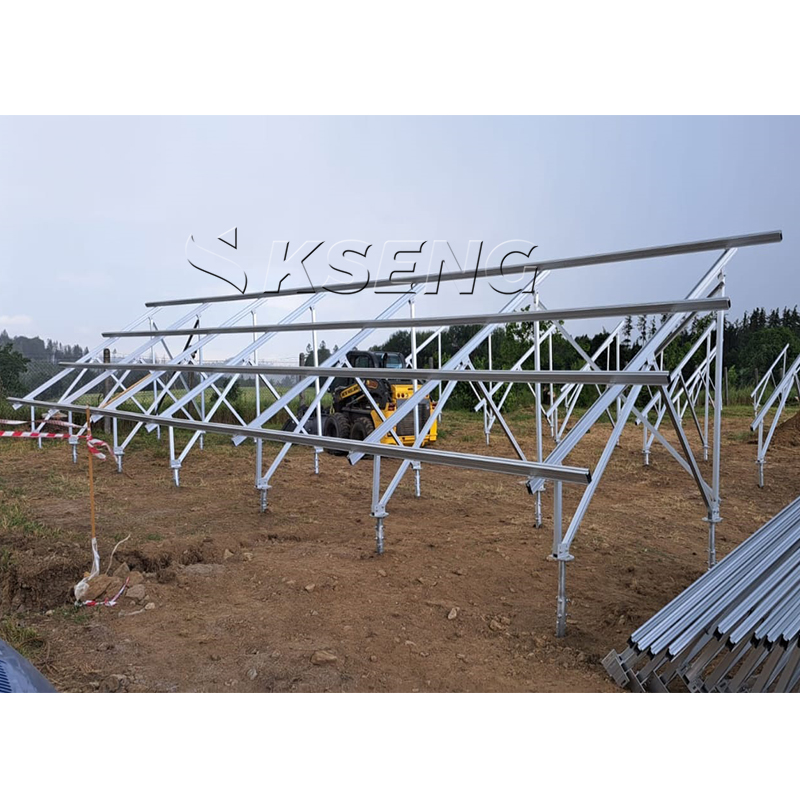
Your choice of structural material heavily influences shipping logistics. It also dictates onsite handling efficiency and long-term maintenance liabilities. Selecting a Solar Ground Mounting System means deciding between steel and aluminum. Each metal serves distinct environmental and financial purposes.
Heavy-gauge galvanized steel dominates utility-scale solar projects. It offers superior tensile strength. This makes steel ideal for high wind and heavy snow load zones. Steel remains highly cost-effective when purchased in massive volumes. However, the sheer weight of steel demands heavy machinery for offloading and onsite staging. Furthermore, steel remains susceptible to eventual rust. If the galvanized zinc layer suffers scratches during installation, corrosion will inevitably begin.
For a lighter alternative, many installers turn to an Aluminum Ground Mount Rack. Aluminum boasts extremely high natural corrosion resistance. This characteristic makes it the premier choice for coastal sites exposed to salt spray. Aluminum is exceptionally lightweight. Your field teams can assemble aluminum racks manually much faster. The lighter weight also lowers freight and shipping costs. The main drawback involves a higher upfront material price. Aluminum also features a lower yield strength compared to heavy-gauge steel, requiring thicker extrusions to meet local structural codes.
You must factor in galvanic corrosion risks when mixing metals. A frequent field error involves bolting aluminum racks directly onto galvanized steel piles without protection. When moisture enters the connection, the dissimilar metals react, rapidly degrading the aluminum. Ensure proper isolation between these components. Always use high-quality dielectric separators or specialized coatings to separate steel from aluminum.
Achieving maximum energy yield is only half the battle. You also need to maintain strict structural compliance. A successful ground mount solar system design requires balancing site topography, extreme weather events, and component limitations.
Wind & Snow Load Compliance: You must design your arrays to meet local structural codes. In the United States, this typically means adhering to ASCE 7-16 or ASCE 7-22 standards. Oversizing the steel to "be safe" destroys your cost-efficiency. Undersizing the frame to save money practically guarantees catastrophic failure during the next major storm.
Topographical Adaptability: Flat sites rarely exist in the real world. You must evaluate racking systems based on their structural tolerances. Look for systems featuring high north-south and east-west adjustability. These systems absorb rolling terrain seamlessly. High adaptability prevents you from needing expensive and destructive site grading operations.
Tilt Angle & Ground Clearance: You need to balance the optimal solar azimuth and tilt against physical clearance requirements. The leading-edge height of the array must clear historical snow depths. Furthermore, vegetation management requires adequate space beneath the panels. If you utilize bifacial modules, you need higher ground clearance to maximize albedo reflection from the earth below.
Assume that heavily sloped sites will require customized racking layouts. Do not rely on off-the-shelf continuous rows if your site exceeds a 10% grade. Articulating joints and stepped racking configurations become necessary to follow the land's natural contours. Forcing straight racks onto curved terrain places undue stress on the structural connections.
A racking system that looks perfect in CAD software can bleed capital in the field. Field realities rarely match the blueprint perfectly. You must address installation challenges proactively to keep construction schedules on track.
Mechanical installation consumes the largest portion of your project schedule. Focus on these three critical rollout factors to mitigate delays.
Adjustability Tolerances: Prioritize racking systems that offer substantial vertical and horizontal adjustability. Pile drivers rarely install posts perfectly plumb or perfectly spaced. The above-ground racking frame must absorb a reasonable degree of human error. Slotted connection holes and sliding clamps provide the necessary flexibility to correct misaligned piles.
Part Count Complexity: Systems utilizing hundreds of small loose fasteners dramatically increase labor hours. Dropped nuts and bolts delay progress and frustrate crews. A high part count also increases the risk of missing components during shipment. Look for racking manufacturers offering pre-assembled structural parts. Minimal-tool locking mechanisms and pop-up trusses save countless hours in the field.
Site Prep & Phasing: Concurrent civil work creates major hazards. Trenching for electrical conduits directly alongside mechanical racking assembly causes traffic jams. You must highlight the risk of overlapping site prep phases. Proper staging of structural materials at the exact row locations minimizes double-handling. Moving steel twice wastes money and exhausts your workforce.
When you purchase structural racks, you are not just buying metal. You are actually buying the engineering liability and procurement reliability of the vendor. Selecting the wrong partner exposes your company to massive financial risk.
Evaluate potential racking partners across three non-negotiable dimensions before signing a purchase order.
In-House Engineering Capabilities: Does the manufacturer provide site-specific structural PE (Professional Engineer) stamps? Or do they push that liability onto your internal team? A credible partner will analyze your geotech report and provide stamped structural drawings guaranteeing their system will survive local wind loads.
Supply Chain Transparency: Assess the manufacturer's lead times honestly. Ask them about their sourcing strategies for raw steel and aluminum. Determine their ability to stage deliveries matching your exact construction phases. Receiving all materials on day one clutters the site. Staggered, just-in-time deliveries keep staging areas clean and organized.
Warranty Terms and Conditions: Look past the standard "20-year" marketing headline. You must evaluate the actual fine print. Determine what specific environmental conditions void the warranty. Highly corrosive soil, improper pile driving techniques, or specific cleaning chemicals often nullify coverage. Ensure the warranty terms match your specific site realities.
We advise installers to send their finalized geotechnical report and site topography map to two or three vetted manufacturers. Request comparative preliminary layouts. Ask for detailed Bill of Materials (BOM) quotes. Comparing these quotes side-by-side reveals which vendor truly optimized the steel design for your specific terrain.
Successful ground mount deployments rely heavily on meticulous upfront planning. You must match the foundation type directly to the soil composition to prevent costly drilling or pull-outs. Selecting materials aligned with site environments ensures long-term durability against rust and corrosion. Furthermore, utilizing highly adjustable racking systems forgives inevitable minor field errors, keeping your labor budgets intact.
Do not bypass rigorous geotechnical testing simply to save a few days on the schedule. Skipping these tests remains the leading cause of massive construction delays. Protect your margins by engineering the solution correctly the first time. Contact our engineering team today for a site-specific design consultation and a racking quote tailored perfectly to your project's soil and load requirements.
A: Standard off-the-shelf ground mount systems typically handle slopes between 10% and 15%. If your site exceeds this gradient, standard fixed racks will experience excessive stress. You will need specialized articulating racks or step-configuration designs to accommodate rolling, steep terrain without requiring expensive site grading.
A: You prevent frost heave by embedding the piles well below the local frost line. The specific depth depends on regional climate data. In extremely cold climates where deep driving is difficult, we strongly recommend using helical ground screws. The structural threads anchor deeply into the stable earth, resisting upward expansion forces.
A: Yes, but you must prevent direct physical contact between the two metals. Combining aluminum and galvanized steel creates a high risk of galvanic corrosion when exposed to moisture. You must install proper isolation barriers, such as dielectric separators or specialized rubber gaskets, between the aluminum brackets and the steel posts.
A: We recommend a standard ground clearance of 24 to 36 inches for bifacial modules. This height provides optimal space for albedo reflection, allowing the rear side of the panels to absorb maximum bounce light. This clearance also ensures shedding snow does not pile up and block the lower edge of the array.