
Views: 0 Author: Site Editor Publish Time: 2026-09-20 Origin: Site


A ground solar mounting system is the structural framework used to install photovoltaic (PV) modules on open land. A properly designed system connects solar modules to foundations and transfers structural loads safely to the ground while maintaining the required module orientation, tilt angle and array geometry.
Ground-mounted solar systems are widely used in commercial, industrial and utility-scale photovoltaic projects because they provide greater flexibility in site layout, array orientation and system capacity compared with many rooftop applications.
The design and installation of a ground solar mounting system generally involves six key stages: site assessment, structural design, foundation selection, mounting structure installation, PV module installation, and final inspection.
A ground solar mounting system is a PV mounting structure installed directly on the ground rather than on a building roof.
A typical ground-mounted solar system consists of:
Solar PV modules
Mounting rails
Beams or cross members
Front and rear posts
Mid clamps and end clamps
Structural connectors and fasteners
Ground screws, piles or concrete foundations
Electrical and grounding interfaces
The mounting structure supports the solar modules and transfers loads caused by module weight, wind, snow and other environmental conditions to the foundation and soil.
For large photovoltaic projects, the mounting system is normally engineered according to the site conditions, module specifications, array configuration and applicable local structural standards.
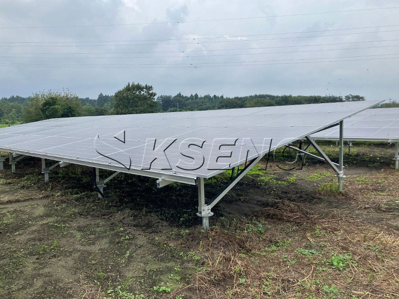
A reliable ground solar mounting system starts with site-specific engineering rather than selecting a standard structure without evaluating the installation environment.
Before designing the mounting structure, the project site should be evaluated for:
Terrain and slope
Soil characteristics
Groundwater conditions
Wind speed
Snow load
Seismic conditions
Flood risk
Corrosion environment
Vegetation and drainage
Access for construction equipment
Terrain conditions directly influence foundation selection, post length, array layout and installation methods.
For relatively flat sites, standard fixed-tilt ground mounting structures can often be used. Sloped or uneven sites may require customized post heights, adjustable structures or different foundation configurations.
The module layout determines the geometry of the entire ground solar mounting system.
Key parameters include:
Module dimensions
Module orientation
Portrait or landscape installation
Number of modules per row
Row spacing
Tilt angle
Inter-row shading
Maintenance access
Cable routing
The layout should balance land utilization, solar energy production, construction efficiency and maintenance requirements.
Adequate row spacing is particularly important because insufficient spacing can increase inter-row shading and make maintenance more difficult.
The tilt angle determines the angle between the PV module surface and the horizontal plane.
A fixed-tilt ground mounting system normally uses a predetermined angle based on factors such as:
Project latitude
Solar resource
Energy production objectives
Land availability
Wind conditions
Snow accumulation
Module technology
Some ground mounting systems also support adjustable tilt angles. Adjustable systems can provide greater flexibility when project conditions require changes to module inclination.
Structural design should consider all relevant loads acting on the solar mounting structure.
Typical design loads include:
Dead Load
The dead load includes the weight of:
PV modules
Rails
Beams
Posts
Clamps
Fasteners
Other structural components
Wind Load
Wind can create both downward pressure and uplift forces on solar modules and mounting structures.
The structural design should consider local wind speed, module inclination, array geometry, terrain category and other applicable engineering parameters.
Snow Load
In regions with significant snowfall, the mounting structure must be designed to withstand the applicable snow load while considering snow accumulation on inclined PV modules.
Seismic Load
Projects located in seismic regions may require additional structural calculations and foundation considerations.
The final design should follow the applicable local building codes, PV structural standards and project engineering requirements.
The foundation is one of the most important parts of a ground-mounted PV system because it transfers structural loads into the soil.
The appropriate foundation depends on soil conditions, structural loads, construction equipment, project scale and local regulations.
A solar ground screw is a helical steel foundation that is mechanically installed into the soil.
Ground screws can be suitable when the soil conditions allow screw installation and when the project requires a relatively fast foundation installation process.
Potential advantages include:
Reduced concrete usage
Fast installation
Less wet construction work
Suitable for selected soil conditions
Potentially easier removal or relocation
Kseng provides several types of solar ground screws, including common, adjustable and large-blade configurations.
However, ground screw selection should be based on actual soil investigation and project-specific load calculations rather than using one screw configuration for every site.
Pile foundations use steel posts driven into the ground to create the structural support for the PV mounting system.
Driven piles are commonly considered for large ground-mounted and utility-scale solar projects where suitable soil conditions and construction equipment are available.
The pile length and profile should be determined according to:
Soil properties
Required embedment depth
Structural loads
Wind conditions
Corrosion requirements
Installation method
Kseng's pile ground mounting solutions are designed for different terrain conditions and can use ground screw or concrete pile foundations depending on the project configuration.
Concrete foundations can provide a stable foundation solution for ground-mounted solar structures, particularly where soil conditions or project requirements make driven foundations unsuitable.
A concrete foundation system may be considered for:
Difficult soil conditions
High structural loads
Certain rocky sites
Projects requiring engineered concrete foundations
Kseng's concrete foundation ground mounting structure uses AL6005-T5 aluminum components and is positioned for utility-scale, commercial and industrial solar applications.
A typical ground solar mounting structure consists of several interconnected components.
Posts transfer loads from the upper structure to the foundation.
They also determine the elevation of the PV array and help maintain the required module geometry.
Beams connect the posts and support the rails.
They distribute structural loads across the mounting structure and maintain the alignment of the solar array.
Rails provide the direct mounting interface for the PV modules.
They are commonly connected to beams and secured with module clamps.
Mid clamps secure adjacent modules along the rail, while end clamps secure the outer edges of the module array.
Bolts, nuts, washers and structural connectors join the individual components into a complete PV mounting structure.
Material compatibility and corrosion resistance should be considered when selecting fasteners and connectors.
Kseng's PV mounting structure product range includes columns, beams, rails and connectors as key structural components of PV mounting systems.
The installation process should follow the approved structural drawings and project-specific installation instructions.
Before installation:
Confirm the site boundary.
Verify the mounting layout.
Mark foundation positions.
Check access routes.
Remove obstacles where required.
Confirm the ground elevation and terrain conditions.
Accurate site preparation helps prevent cumulative installation errors across large PV arrays.
Install the selected foundation according to the engineering design.
For ground screws, installation equipment drives the screw to the specified depth and position.
For piles, the posts are driven to the required embedment depth.
For concrete foundations, excavation, reinforcement, concrete placement and curing should follow the approved engineering specifications.
Foundation positioning and installation tolerances should be checked before the upper mounting structure is assembled.
After the foundation is completed, install the posts and connect them to the beams.
At this stage, installers should verify:
Post alignment
Elevation
Verticality
Spacing
Bolt connections
Array orientation
Accurate structural alignment is important because small positioning errors can accumulate across long rows.
Install the mounting rails on the beams according to the approved module layout.
The rails should be aligned to provide a consistent mounting surface for the PV modules.
Check rail spacing, connection points and fastener installation before installing the modules.
Position the PV modules according to the approved array layout.
Use mid clamps and end clamps to secure the modules to the mounting rails.
During installation, installers should check:
Module alignment
Clamp position
Fastener tightening
Module spacing
Cable routing
Potential contact between modules and structural components
The completed mounting system should be inspected before commissioning.
The inspection should include:
Foundation position
Structural alignment
Fastener installation
Clamp installation
Module position
Electrical grounding
Cable management
Structural damage
Corrosion protection
Site safety conditions
Any installation issue should be corrected before the PV system is placed into operation.
There is no single mounting structure suitable for every solar project.
The selection should consider five main factors.
Soil investigation helps determine whether ground screws, driven piles or concrete foundations are appropriate.
Wind, snow and seismic conditions influence the structural design and foundation requirements.
Flat, sloped and uneven terrain may require different structural configurations.
Residential, commercial, industrial and utility-scale projects can have different requirements for installation speed, structural capacity and cost optimization.
Aluminum and steel are widely used in PV mounting structures.
Aluminum provides a lightweight and corrosion-resistant option for many PV applications, while galvanized steel provides high structural strength and is widely used for ground-mounted structures.
The appropriate material should be selected according to structural requirements, environmental conditions, installation methods and project economics.
Kseng provides solar mounting and tracking solutions for residential, commercial, industrial and utility-scale PV applications.
Its product range includes ground mounting systems, solar farm mounting systems, solar ground screws and solar tracking systems.
Kseng's ground mounting solutions include different structural and foundation configurations for project-specific requirements. Its pile ground mounting system, for example, is designed for flat, uneven and sloped terrain conditions and supports customized dimensions.
For projects requiring concrete foundations, Kseng also offers AL6005-T5 aluminum ground mounting structures designed for commercial, industrial and utility-scale applications.
The final mounting structure should always be selected and engineered according to the project site, local standards, module specifications and structural load requirements.
Before starting installation, project teams should verify the following:
| Design Item | Key Consideration |
|---|---|
| Site survey | Terrain, slope and access |
| Soil investigation | Soil strength and foundation suitability |
| Wind load | Local design wind speed |
| Snow load | Snow accumulation and structural capacity |
| Seismic load | Applicable seismic requirements |
| Module layout | Portrait/landscape and row configuration |
| Tilt angle | Latitude, energy yield and site conditions |
| Foundation | Ground screw, pile or concrete |
| Structure | Posts, beams, rails and connectors |
| Fasteners | Material compatibility and corrosion resistance |
| Installation | Alignment, torque and tolerances |
| Inspection | Structural and electrical quality control |
A ground solar mounting system is a structural system used to install photovoltaic modules on the ground. It normally includes foundations, posts, beams, rails, clamps and fasteners.
The appropriate foundation depends on soil conditions, structural loads, terrain, environmental conditions and local engineering requirements. Ground screws, driven piles and concrete foundations are common options.
Ground-mounted and rooftop PV systems serve different site conditions. Ground-mounted systems can provide greater flexibility in array orientation, tilt and layout, while rooftop systems can utilize existing building space. The appropriate solution depends on the project site and engineering requirements.
There is no universal installation depth. The required depth depends on soil properties, structural loads, screw design and local engineering requirements. A soil investigation and structural calculation should be used to determine the project-specific installation depth.
Common materials include aluminum alloys, galvanized steel and stainless steel fasteners. Material selection depends on structural requirements, environmental exposure, corrosion conditions and project design.
The service life depends on structural design, material quality, corrosion protection, installation quality and environmental conditions. Properly engineered and maintained PV mounting systems are designed for long-term outdoor operation.
The project team should check the site survey, soil conditions, structural calculations, foundation design, module layout, wind and snow loads, installation drawings and applicable local standards before construction.
Ground solar mounting system design is a combination of structural engineering, foundation engineering, PV layout planning and installation technology.
A reliable system starts with a detailed site assessment and continues through foundation selection, structural design, precise installation and final inspection.
For commercial, industrial and utility-scale PV projects, the mounting system should be engineered according to actual site conditions rather than relying on a one-size-fits-all configuration.
By combining appropriate foundation technology, corrosion-resistant materials, accurate structural design and efficient installation methods, a ground-mounted PV system can provide a stable structural platform for long-term solar energy generation.



